Kill switch wiring

JoshS

New member
I did a couple of searches on this forum and elsewhere, and found some good discussions, but really couldn't convince myself of the right thing, and I'm no electrical engineer. I'm a visually-oriented guy, so maybe using these diagrams you can all help me.

Given the wiring diagram below, can I place a simple single-pole switch in the circuit that runs around the left and top of the diagram, either right before or right after the big 200A fuse? Or do I need one of the multi-pole switches that somehow connect into the alternator circuit?

I'm thinking the simpler approach will work. The junction point with the 8 large fuses you see eventually leads to the ignition switch, among other places.

WiringDiagram-e36z3_99.jpg


If I need the multi-pole switch, can someone please explain to me how to wire it? I found this diagram below from Pegasus, but it's not descriptive enough for me to know what to do with it. Pegasus seems to say that all cars with alternators need these multi-pole switches, but based on what I've read elsewhere, as long as the alternator is still connected to the battery, then the single-pole switch should work?
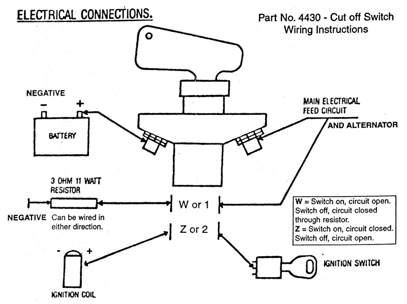
4430-inst.jpg


Thanks for the help!
 
Keep in mind that the kill switch must not only stop the engine but should isolate vehicle wiring from the battery to minimize a fire threat. The Red connection in my diagram when wired as shown, does just that. I lack enough time to give you more detail, but that Pegasus sourced diagram is concise and correct, may just be some hlepful hints for a electro-newbie!

this may help people explain it.......

4430-inst.jpg


In answer to the multi-pole switch comment. The Pegasus is 3PST 2 poles are NO and 1 pole is NC.

The Red/Green and Violet/Yellow are N.O. and the Blue/Orange is N.C.
 
putting any electric fuel pump on the feed with the ignition coil is a good idea too.

When you throw the Kill switch to OFF, here's what happens:

1 - the battery is obviously otally disconnected
2 - the ignition and fuel shut down
3 - the alternator gets a small load to protect its diodes etc.
 
My confusion about the Pegasus diagram is that there is no simple wire from the ignition switch to the coil in my car. My car has all sorts of fancy electronics, six ignition coils, an electronic anti-theft immobilizer, a multi-pole ignition switch with several wires on the output side, etc.

It's just not obvious what wire to disconnect to shut the car off. I was hoping that the simpler thing would in fact kill the engine, based on, among other things, this thread.
 
My confusion about the Pegasus diagram is that there is no simple wire from the ignition switch to the coil in my car. [/b]

Locate the group of wires that connect to the "run" position on your ignition switch, route that group through the kill switch "ignition" path.
 
If you isolate the battery with the main circuit, and run the alternator field circuit through the normally-open circuit with the resistor, you'll be fine.

The resistor circuit is there primarily to protect the contacts of the main circuit (and really should be used on any car, regardless of what charging system you have). If you simply open up such a high-current circuit as the battery, that load has to go somewhere; without the resistor circuit it arcs the contacts of the main switch. Giving the load someplace to slowly drain protects those contacts.

Further, if the field circuit of an alternator stays energized (as it can with a charning system) then it can harm the alternator.

So, by running the field circuit of the alternator through the NO circuit with resistor, you resolve both problems.

As far as Tech is concerned, if they can reach over and shut off your car entirely with that switch (and trust me, they'll test it) then it's fine. They/we don't give two shakes what it does to the components of the charnging system; their concern is safety, your concern is making sure it doesn't hurt stuff...
 
Locate the group of wires that connect to the "run" position on your ignition switch, route that group through the kill switch "ignition" path.
[/b]

I'm sure I could find the right thing. There is a wire at the coil packs that feeds all six, I could probably pick it up there instead of at the switch. At the switch, there is a line that's hot in run, and a line that's hot in both run & start. Seems like to kill the ignition it would be the second one. Or I could get them at the coils.

Between the switch and the coils is so much electronics that you really can't tell what's going on.

But ... what I really want to know is, will the first approach work? It seems like it. The alternator output side (the B+ terminal) would be connected directly to the battery, even when the switch is off, so it would have somewhere to drain. However, with the switch off, there would be no contact between the battery/alternator and the ignition. Isn't this simple approach the best approach?

If you isolate the battery with the main circuit, and run the alternator field circuit through the normally-open circuit with the resistor, you'll be fine.
[/b]
Forgive me Greg ... I don't understand a word you just said! I don't know what a field circuit is, and I don't really understand what you mean by "main circuit" either.

Can you draw me a picture?

I understand the principle of protecting things with the resistor ... I just don't understand why the first approach doesn't do that.
 
I don't really understand what you mean by "main circuit"...[/b]
The main circuit from the battery to the car, just as in the drawings above.

I don't know what a field circuit is...[/b]
VERY basically put, alternators work on the concept of comparing a circuit in the car to what voltage it's putting out, always trying to keep them equal to its setting. In the case of a 12V car, that's about 13.5 volts. If that secondary circuit, the field circuit, gets low on voltage the alternator puts out more; if it gets high, less.

Therefore, with an alternator, if you cut off the battery only then as the field circuit voltage drops the alternator tries to out out more and more voltage. Eventually the field circuit voltage will drops too low and the alternator goes offline, but it's not instantaneous, and in the interim the alternator continues trying to charge pu the system to ~13.5V.

However, if you open this field circuit with a switch or relay then the alternator sees zero voltage and drops offline.

So, you can wire the car one of two ways: wire the kill switch's smaller secondary contacts such that it disconnects the field circuit and the alternator goes offline, system voltage drops to zero, and the car quits running due to lack of electrical power; or, you can wire the ignition through those secondary contacts so the car quits running and the alternaotr stops producing power due to lack of rotation.

Either way works fine, simply choose the method that is most convenient for your car and kill switch location. - GA
 
VERY basically put, alternators work on the concept of comparing a circuit in the car to what voltage it's putting out, always trying to keep them equal to its setting. In the case of a 12V car, that's about 13.5 volts. If that secondary circuit, the field circuit, gets low on voltage the alternator puts out more; if it gets high, less.

Therefore, with an alternator, if you cut off the battery only then as the field circuit voltage drops the alternator tries to out out more and more voltage. Eventually the field circuit voltage will drops too low and the alternator goes offline, but it's not instantaneous, and in the interim the alternator continues trying to charge pu the system to ~13.5V.
[/b]
Thanks! I get it. The point of the secondary kill circuit is to reduce the amount of time it takes to get the alternator fully off-line.

Now, just out of curiosity, what harm is caused during this duration of time if the alternator main circuit is still connected to the battery, as my original question asked?
 
My confusion about the Pegasus diagram is that there is no simple wire from the ignition switch to the coil in my car. [/b]

Locate the group of wires that connect to the "run" position on your ignition switch, route that group through the kill switch "ignition" path.

2nd post by accident...... how to delete??
 
Locate the group of wires that connect to the "run" position on your ignition switch, route that group through the kill switch "ignition" path.
[/b]
Yeah, there is no "run" terminal of the switch. There is one terminal hot in acc/run/start, and another that's hot in run/start. (There are others too, but those are the ones used that are hot in run). The point is that there are two of them, and the switches on the market have only one.

I still don't get why the simpler approach won't work or could cause any harm.
 
...what harm is caused during this duration of time if the alternator main circuit is still connected to the battery, as my original question asked?[/b]

The "generally accepted" problem is one of damage to the alternator; alternators REALLY WANT to have some kind of accumulator to dampen the positive and negative spikes it produces, and that's the battery's job. You disconnect that battery from the equation and you run the risk of alternator damage or possibly runaway.

"Runaway"? From a safety aspect, theoretically an alternator-equipped car can continue to run with the battery disconnected. The car will run as long as the electrical system has voltage; the alternator will continue to put out voltage as long as the field circuit is "excited"; the field circuit will remain "excited" as long as the alternator is putting out voltage. See the Catch-22 there?

I've never tried shutting of my car with the kill switch without the alternator/ignition properly wired, so I can't say that's what will happen for sure. But I certainly don't want to try it on my car. Maybe this is a good one for Mythbusters?

The goal is to get the car to stop running, with all electrical equipment de-energized. You'll do that either by stopping the alternator from turning (by shutting off the ignition) or getting the alternator to stop putting out electricity by opening the field circuit (thus killing the ignition due to lack of electricity). Either way works.

I can assure you that, upon presenting your car to an SCCA tech inspector for its logbook, one of the very first things the inspector will do is ask you to start the car then he/she will reach over and flip off the master kill switch to see if the car stops. If you're comfortable having someone do this using just the battery circuit, and it works, then you're all set... - GA
 
I can assure you that, upon presenting your car to an SCCA tech inspector for its logbook, one of the very first things the inspector will do is ask you to start the car then he/she will reach over and flip off the master kill switch to see if the car stops. If you're comfortable having someone do this using just the battery circuit, and it works, then you're all set... - GA
[/b]
I understand that. But somehow we're not understanding each other. It's probably me because I didn't stay at a Holiday Inn Express last night.

Based on the diagram in teh first post, the car is wired such that the positive connection of the battery has two leads, one which connects to the alternator (let's call it "wire 1") and one which connects to the ignition system and the rest of the car's electrics ("wire 2").

If the car is running, and the alternator is producing output, that output will be going straight to the battery on wire 1, and then from the battery to the ignition system on wire 2.

If I put a switch in the middle of wire 2, then when that circuit is broken, there will be no voltage on the field circuit, either from the battery or from the alternator, because both the alternator and the battery are upstream of the switch. Further, the alternator isn't left hanging with nothing to absorb its remaining energy, because it can still reach the battery on wire 1. Seems to solve all of the problems. And yet I keep reading between the lines of what you are saying, in which you are implying that either this will not stop the engine, or maybe you're saying that it will stop the engine but will harm the car's alternator or other systems.

What the heck am I missing?
 
What the heck am I missing?[/b]

GCR 17.27: "The master switch shall be installed directly in either battery cable and shall cut all electrical circuits..." (my emphasis) I was describing above with this requirement as an assumption.

You don't have a choice: the battery must be completely isolated from the rest of electrical system. If you did it as you describe, then the remainder of the car's electrical system is still getting juice from the battery.

Remember: it's not JUST about getting the car to shut off; it's about getting the car to shut off AND have no charge to ANYTHING else in the car. Picture running fuel pumps while you're upside down, or battery cables chafing against smashed sheet metal with dripping fuel, or sparking instrument cluster wires 2 feet from your fasce, and so forth.

You will have to remove those two wires from the battery, attach them to a common block, run a cable from that block to the kill switch (or run the two wires on ring terminals to one side of the switch), then from there to the battery. Alternately, you can bisect the battery ground wire with the kill switch. THEN, you run either the ignition or alternator field circuit through the smaller terminals, and now you're golden.
 
GCR 17.27: "The master switch shall be installed directly in either battery cable and shall cut all electrical circuits..." (my emphasis) I was describing above with this requirement as an assumption.
[/b]
Good point, okay, now we're done. What that also means is that the other thread from this forum that I referred to earlier was giving bad advice, as it recommended connecting the alternator directly to the battery.

So thanks. Sorry that it took us so long to get there.
 
"Runaway"? From a safety aspect, theoretically an alternator-equipped car can continue to run with the battery disconnected. The car will run as long as the electrical system has voltage; the alternator will continue to put out voltage as long as the field circuit is "excited"; the field circuit will remain "excited" as long as the alternator is putting out voltage. See the Catch-22 there?

I've never tried shutting of my car with the kill switch without the alternator/ignition properly wired, so I can't say that's what will happen for sure. But I certainly don't want to try it on my car. Maybe this is a good one for Mythbusters?
[/b]

The car keeps running. My car had a single pole switch on it when I got it that just disconnected the battery from the car. I didn't know any better at that point. I go to my first ever annual tech and the first thing the inspector does is throw the kill switch. The car keeps on running. My comment was "It's not supposed to do that is it." I have no idea how Bob passed annual. I replaced it with a three pole switch that disconnects the computer signal to the ignition coil. The car now stops. Moral of the story: You need something other than just disconnecting the battery from the car.

David
 
GUYS! keep this simple AND reliable. Let the kill swx main posts disconnect the battery.
Let one loww current kill swx ground the grounded leg of the ignition coil, killing the engine but leaving all run consumers (fuelpump, etc) to load the alt as it coasts to a stop. (if you don't have a single coil, then put both legs of the low current circuit across the crank sensor, etc.
Not only is this a very simple circuit, but it fails safe in regard to cutting out the engine in competition-if the low current switch gets resistive/corroded, it doesn't effect running, just killing. Phil
 
The car keeps running. My car had a single pole switch on it when I got it that just disconnected the battery from the car. I didn't know any better at that point. I go to my first ever annual tech and the first thing the inspector does is throw the kill switch. The car keeps on running. My comment was "It's not supposed to do that is it." I have no idea how Bob passed annual. I replaced it with a three pole switch that disconnects the computer signal to the ignition coil. The car now stops. Moral of the story: You need something other than just disconnecting the battery from the car.

David
[/b]

Josh,

You'll want to wire the two pole switch to the two wires that run from the battery to the engine compartment on the passenger side. There should be an ignition relay in your circuit, I don't have the Bently manual in front of me right now, but I do remember it being there, it's in the immobilizer part of the curcuit. Anyway, the problem is that the switch just removes the 12v. it really needs to ground out the alternator and computer, to make the circuit dead, this is what the relay does ground the curcit when it's off, applies 12v. when it's on. This is where the alternator feedback can keep the motor running with the battery disconnected when there's no path to drop the voltage in the field wire. I wired the Battery Cutoff Switch (BCS) in series with a toggle switch on the small wire, this energises the relay and ungrounds the alternator field, computer key switch wire, and fuel pump wire. This way the BCS and the toggle both kill the motor, but the BCS removes all electricity from going into the engine bay. I can tell you the wire numbers you want to look for and the colors if you like, but the BCS should be along the main battery wire running along the passenger side. Good luck,

James
 
GCR 17.27: "The master switch shall be installed directly in either battery cable and shall cut all electrical circuits..." (my emphasis) I was describing above with this requirement as an assumption.

You don't have a choice: the battery must be completely isolated from the rest of electrical system. If you did it as you describe, then the remainder of the car's electrical system is still getting juice from the battery.

....

[/b]

Greg,

Though I'd mention one exception which is electrically actuated fire systems must be hot at all times even when the BCS is off. If it's a pull cable like mine then all dead is good.

James
 
Back
Top